Replacing a Williams System 11 Display Board
I have a Road Kings pinball machine with a dead Player 4 display. In addition, the remaining display have segments that flicker or don’t work. Probing the display board with my scope seems to indicate some of the driver chips have failed outputs.
As near as I can tell, neither the gas-plasma displays nor the associated driver chips are made any more, and the used replacement parts are super expensive.
Given that, I decided to see what it would take to replace all the displays with modern 16 segment LEDs. In addition to having working displays, they would use less power and produce less heat, hopefully extending the life of the rest of the components in the machine.
The Williams System 11 display board is powered by +5v, +90v, and -100v, and the +5v rail is perfect for modern electronics.
The display board is driven by the CPU board with 32 Strobe lines (STB 1-16, STB 1’-16’), each corresponding to a digit, and 32 segment lines (a-r, com, dot, a’-r’, com’, dot’).
The Road Kings machine has two 7 digit 14 segment displays (player 1 & 2), two 7 digit 7 segment displays (player 3 & 4), and two 2 digit 7 segment displays (credit & match), for a total of 18 digits. The display board schematics show it also supporting displays for players 5 & 6, with 6 digits/14 segments each, presumably used on a different pinball machine.
Investigating the strobe and segment lines with the Saelea logic analyzer revealed that the timing of the lines is pretty loose, which seems to be typical for everything in these old machines. I as expecting the segment lines to be setup and stable when the strobe line activated, but the timing is all over the place. Sometimes segments are driven before the strobe, sometimes not until sometime after the strobe is enabled. The relatively low refresh rate and decay rate of the gas displays seems to prevent any slight timing issues from being noticed.
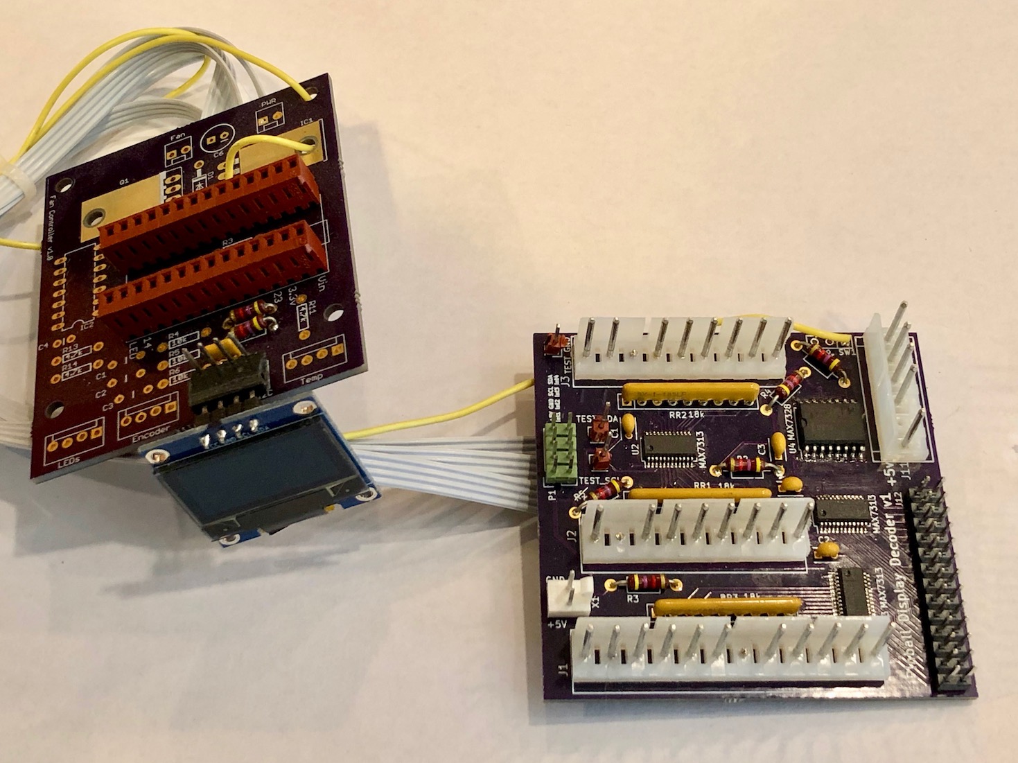
My first idea to decode the lines involved attempting to read all the lines using I2C port expanders connected to a Teensy 3.2 driving a small OLED display. The Teensy would repeatedly read all the lines, interpret the data, and display “14 segment” output on the OLED screen.
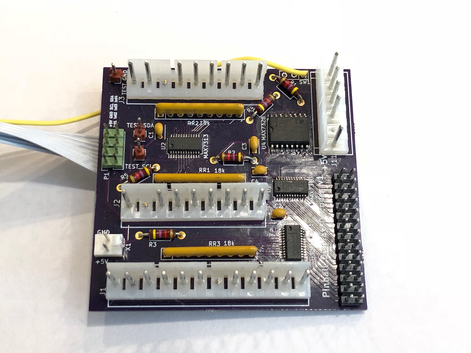
Shortly after getting the boards put together and I got some code running, I discovered the I2C port expanders were way too slow to sample the 40 or so lines needed for the displays (not all lines are used on this machine). I had hoped to be able to sample significantly faster than the refresh rate and detect line transitions, but that did not work out.
Next idea was to see if a Teensy could read the lines directly fast enough to process the data. To do this, I repurposed a leftover board from another project and bodged in wires from Teensy pins directly to the connectors from the CPU board. The Teensy would draw the segments it was sampling on the attached OLED display.
The new setup was a significant improvement, though I could only sample less than half the lines (not enough I/O pins on the Teensy 3.2). The Teensy was able to sample the lines fast enough to reliably detect transitions and make decisions about what was happening.
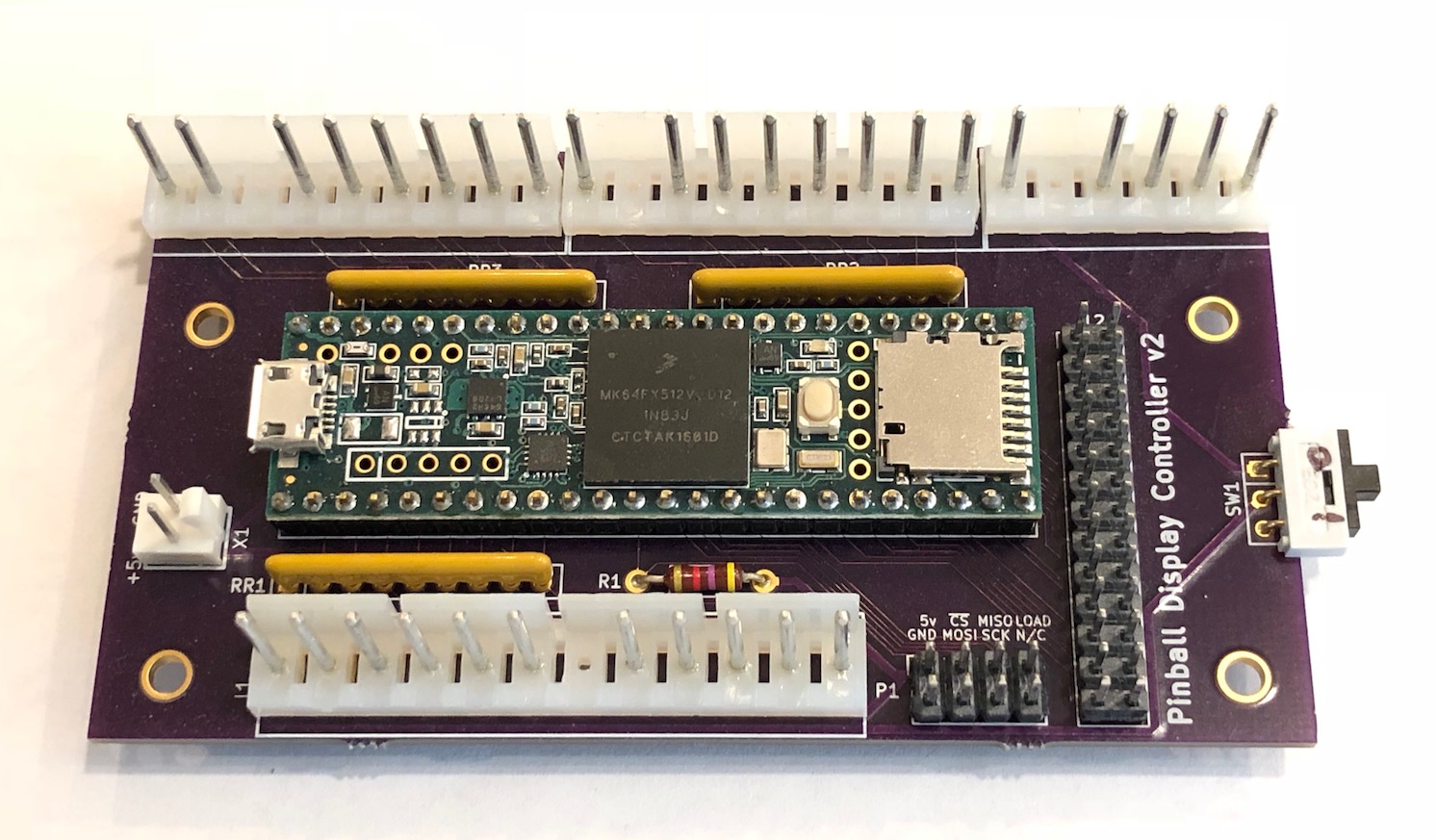
Next step was to use a Teensy 3.5, which has enough I/O pins to sample every line directly, and just enough left over to drive the OLED display.
Given the irregular timing of the lines (the timing actually varies by digit), capturing good data proved somewhat challenging. My strategy was to detect the transition of a strobe time, wait a fixed settling time, then sample the segment lines for a fixed period, and calculating the display based on the results.
After some trial and error, I did eventually get some working results. I was able to get mostly correct digits on the OLED, but one segment was consistently wrong. The logic analyzer consistently showed the correct data arriving from the CPU board, and I could not find any fault in the code I had written. I eventually discovered there was a manufacturing defect with the Teensy 3.5. That I/O line would not read the correct value without pressure applied to the top of the microcontroller. I assume there was a sketchy solder joint on the BGA pads.
So, this was a partial success. I could read the lines fast enough to get pretty good data, but I was now limited by bandwidth to the cheap OLED display I was using. It took long enough to update the display that I would miss a full strobe cycle and drop frame samples.
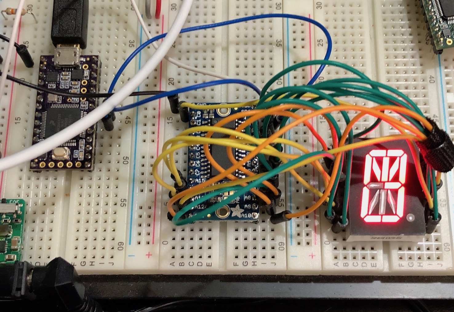
I’m now working on being able to drive actual 16 segment LEDs from the Teensy. I’m using these common cathode LEDs I purchased off AliExpress on a board I milled out with the Bantam Tools PCB mill.
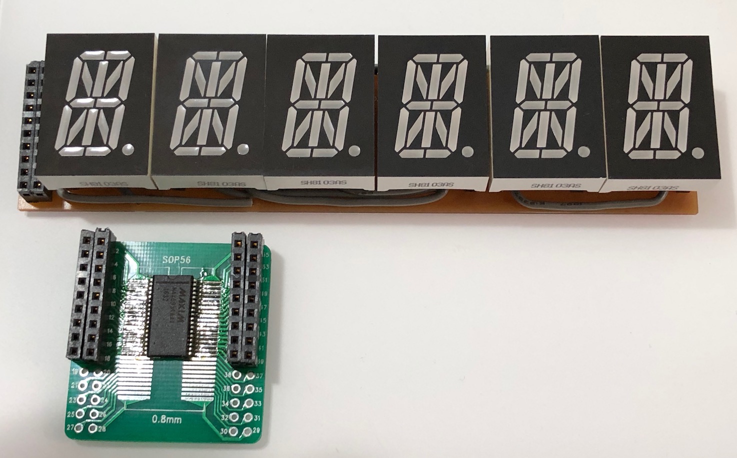
I stared with the Maxim 6954, assuming it allowed for driving all 16 segments individually, but discovered that it does not. It can drive a 7 segment display individually, but appears to be limited to a glyph lookup for 16 segment displays, which does not cover all possible segment combinations.
I’m now working with the excellent Adafruit LED Matrix Driver Backpack, which breaks out all the pins of the HT16K33 driver chip. This chip is very easy to work with and allows for driving each segment independently.
Next step is to create a couple of new display boards for the backpacks, and a carrier board that connects the backpacks with a Teensy.