Bantam Tools PCB Milling Tips
I’ve had my mill for about two weeks now and thought it would be good to document the things I’ve struggled with as a new user. The Bantam Tools support folks have been super helpful, I can’t say enough good things about them!
These tips may or may not work for you, and may or may not be actual good ideas.
How Long Does It Take to Mill a PCB?
The two boards shown on this page took about 2 hours each. One a bit less, one a bit more. In general, the more you can get the 1/32” bit to be used vs the 0.003” engraving bit the faster it seems to go. You might make several trips back and forth between KiCad (or whatever you are using) and the Bantam app to tweak and optimize the tool paths generated for your gerbers.
How Loud is the Mill?
I have not measured the sound level with an SPL meter (I’ll try to remember to do that with my next project). It’s not horrendously loud, but you won’t want to sit next to it for very long. I have found if I put in my in-ear earphones which seal outside noise out, it becomes a low background drone and I can keep working.
Copper Removal
The software optimizes for not removing any more copper than it thinks is necessary. According to support, this extends tool life and shortens the time required to mill a board. While this is kinda obvious in hindsight it’s not explicitly called out in the documentation.
So, when you mill your first board and there are large islands of copper left between traces (and a lot of smaller ones), this is to be expected with the default settings. The traces should match the gerbers, but the empty spaces will not.
This board is a good example of what the default settings generates.
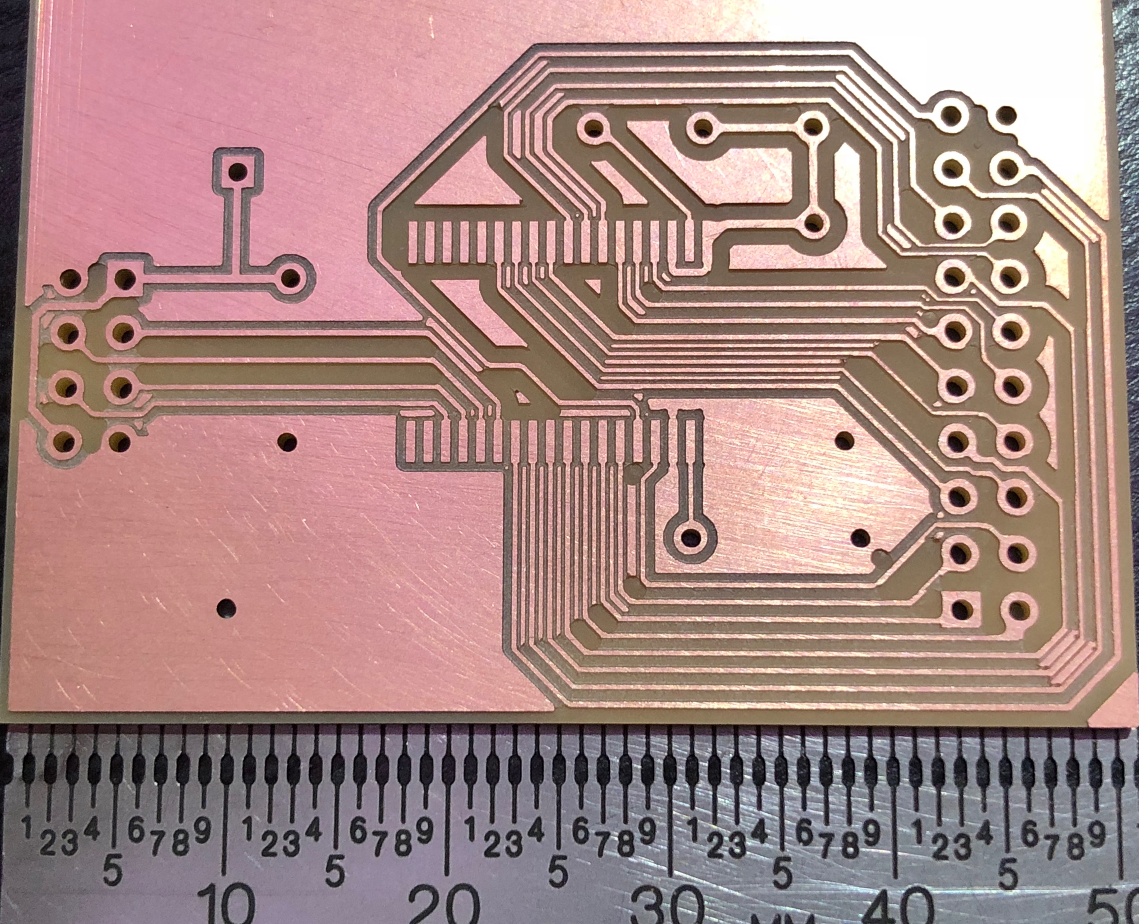
While the large islands of copper might be desirable (free ground planes?), the strips left between the traces and the little random bits can be a problem. It’s not difficult to accidentally get a solder bridge when soldering components, and some of the tiny copper dots may have tiny whiskers from the milling process that remain even after scuffing or sanding. Might be fine, but I’m not confident with the resulting board.
The fix for this is easy. Open the Advanced pane and increase the Trace Clearance until it’s removed all the copper you want.
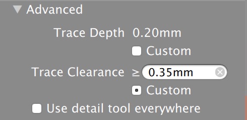
I’ve found that 0.30mm - 0.35mm works for me.
Don’t Let the Computer Sleep
I’ve had a couple of jobs fail in odd ways if the screensaver was running when a tool change prompt should have been displayed. I’m on a Mac, so solution is to set a hot corner to disable sleep and the screensaver and put the cursor there before laving the computer. I filed a bug on this, the software should keep the computer form sleeping. Simplify3D does this really well during long 3D prints.
If the software stops during a tool change, you might be able to recover. In my case, it had finished milling with the 0.003” engraving bit, so I just removed that bit from the Milling Tools list and started the job again. Seemed to work fine.
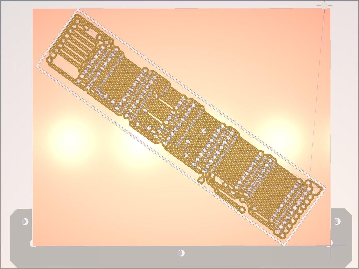
Creative Board Layout
I needed a board that was slightly larger than the stock 4x5 PCBs from Bantam. Rotating the layout let me get a slightly oversized board that would not have been possible otherwise.
Single Sided Boards
I only ordered single sided blanks with my mill (seemed like a good starting point), and of course the first thing I wanted to make is impossible to route with just one side…
The solution is to do all the copper routing possible on the back side, then place vias and add traces to the front copper layer which will be jumper wires when you actually assemble the board. When you load the gerbers into the software, only mill the bottom side.
Mounting and Measuring Fixture Thickness
I’ve been mounting my PCB blanks to a square of Delrin, which is aligned with the basic fixture bracket. I’ve been doing this as I didn’t want to unnecessarily chew up the aluminum spoil board with cuts that were too deep.
The documentation says you should cover the entire back of the PCB with double sticky tape, but having done that once it seems like overkill and it makes it really hard to remove the board. I’ve found that two full width strips of the normal double sticky tapes does just fine.
To set the material thickness and placement without having to manually measure various layers of double sticky tape, I’ve been using this procedure:
- Measure the thickness of the board on all sides with calipers (or at least on the sides you’ll be milling). Note that there is variation between boards, so you need to measure each board before use.
- Attach the PCB probe clip and probe the thickness. This will give you the distance from the top of the board to the aluminum spoil board.
- Subtract the caliper measured thickness from the distance the probe measured. This value is the placement offset.
- Finally, enter the caliper measured thickness as the material thickness.
Engraving
I did try engraving one of the supplied dog tags, and that couldn’t be easier. Just render something as an SVG and off you go. I initially tried this with Inkscape and discovered Inkscape is just horrible on the 5k iMac. Omnigraffle works really well for churning out basic vector art as SVGs.
Final Thoughts
If you have been thinking about getting one of these for knocking out quality prototypes, I highly recommend it. Overall, the mill is a great little machine. The fit and finish are spot on, software works quite well, and their support has been quick and helpful . I’m still working my way through the Fusion 360 tutorial videos, so I’ve not tried machining models yet.